With just one click you can update the driver as well as the rest of the drivers in your system, such as: • Monitors • Audio & Sound • Graphics & Video Adapters • Modems & Network Adapters • Printers • Scanners • Optical Disk Drives • Other Devices This utility works in two simple steps: 1. This utility contains the only official version for Delphi USB interface Driver for Windows XP/7/Vista/8/8.1/10 32-bit and 64-bit versions. Delphi ds150e usb driver update.

A question we are commonly asked is “How do I copy a serial EEPROM chip?”. Serial EEPROMs are the memory chips found in car keys, some radios, PC motherboards and other electronics. They are usually 8 pin and retain data when the unit is switched off, which is why they are used for settings and configuration data. This is also why people want to copy them.
USB SOP8 Serial Eeprom universal device programmer. Supplied with Windows software to read, program and erase the connected eeprom. EEPROM (also E 2 PROM). By applying special programming signals. A typical EEPROM serial protocol consists of three phases.
So, how do you set about copying a serial EEPROM?
Firstly, there are several different types of serial EEPROM chip and the type must be identified. They all use the same method for storing data but how they communicate varies from family to family. The three main types that are used in commercial products are
- 24 Series: These use the I2C two wire protocol
- 25 Series: Use 3 wire SPI communication
- 93 Series: Use Microwire, a variant of SPI
You do not need to know the details of these protocols as the programmer will deal with this, but you do need to read the chip number from the top of the device. The chip could have several numbers including date codes, but the important one has 24, 25 or 93 in it. It will usually start with a letter for manufacturer (AT for Atmel, M for STM etc) but not always and may be followed by a letter or two for series. It will end in a number giving the memory size, in bits not bytes.
Some examples –
- 24AA16, 24LC16 : Microchip 16KBit (2 KB) I2C serial EEPROMs
- AT25C02: Atmel 2Kbit (256 Bytes) SPI serial EEPROM
- M24512: ST 512Kbit (64 KB) I2C serial EEPROM
- 93AA76A, 93AA76B, 93C76B, 93LC76C: Microchip 8Kbit (1KB) Microwire serial EEPROMs.
In most cases, you do need need to worry too much about the manufacturer or series as devices from most manufacturers are the same. So, if you select a similar device from a different manufacturer it will usually read and program the same way, just as long as you choose one from same family (24, 25 or 93) with same memory size.
Obviously, if you can find an exact match in programmer support list then choose that but you won’t damage the reader or the chip by selecting the wrong device. Some programmers can identify the chip type automatically just by connecting them. You will not damage an EEPROM device or corrupt its data if you use the wrong chip selection, it just won’t read it.
Ok, we have identified the serial EEPROM and know what to select in the programmer device list but how do we connect to it? There are two choices, unsolder it and put it in a socket programmer or read it in circuit.
Socket Programming
If you can unsolder the chip from the circuit board, you can drop it into a socket programmer or reader to read it, save the contents and program new devices. Most universal programmers support serial EEPROM chips, so you do not need an expensive product for them.
The Wellon VP-299 Universal Programmer is a low cost unit that can handle all serial EEPROMs. If your serial EEPROM is not a DIL package and is surface mount eg SOIC, then you will need a socket adapter as well.
In Circuit Programming
Also called In System Programming or ISP, this method usually relies on having a header to connect the programmer lead. In most cases, your circuit won’t be fitted with an ISP header but you can use IC test clips to connect to the serial EEPROM directly instead.
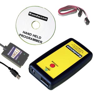
Kanda sell an IC clip pack that will connect to serial EEPROMs in 8 pin through hole (DIP), and 8 pin surface mount (SOIC) packages. These clips can be connected easily to the USB In System Programmer. The programmer software can be used to read the device, save it to a file and program new EEPROMs.
You will need to connect the programmer leads to the correct pin on the IC clip and some more knowledge is needed to do this. First find the device datasheet to get the pin diagram of the device. There are lots of datasheet sites on the web, such as alldatasheets.net or you can try manufacturer site or just type device name plus datasheet into a search engine, e.g, AT24C01 datasheet.
You need to connect GND and VCC pins to programmer in all cases, plus the programming lines. These have different names depending on the family.
Eeprom Technology
- 24 family: These are I2C devices and the programming pins are called SCL and SDA
- 25 family: These are SPI devices with 3 lines called MISO, MOSI and SCK
- 93 family: These are Microwire chips and use DI, DO and CLK
The ISP programmer has an adapter with coloured leads and the manual tells you which colour is which signal for different device families.
Programming Board
Kanda also supply programming boards for their Serial EEPROM ISP programmer, which lets it act as a socket programmer. There is a low cost version with just a standard socket and a more expensive version with a ZIF socket and a SOIC adapter.
Related Information
This simple tutorial will guide users through the process of interfacing an EEPROM chip to a Raspberry Pi using the GPIO pins and performing operations with Python scripts.
Let's start with some basics on EEPROM:
1) CE, OE, WE - What does it all mean?
In order to read, write and erase data from an EEPROM chip, we must first bring the chip at the correct state. This is done using 3 control pins typically named Chip Enable, Output Enable and Write Enable.
Chip Enable controls whether or not the chip is powered up. Depending on the type of chip, connecting this pin to the ground or to voltage will turn the chip on or off. Needless to say, that if we want to perform any operation we need to enable the chip. Disabling the chip allows us to power down the chip while leaving it electrically connected to our circuit. This way the chip consumes less power.
Output Enable is a pin used to tell the chip that you want to read from it. Once again, depending on the chip, connecting this pin to the ground or to voltage will tell the chip to present you with the contents of given memory address (more on that later). Disabling the Output completes the read operation.
Write Enable is similar to Output Enable but used for writing data to the chip. Depending on the type of chip, connecting it to ground or to voltage will make the chip write data to a selected memory address (more on that later).
2) So how do I control the pins?
Eeprom Uses
It is easy! Depending on your EEPROM chip, you enable or disable these pins by connecting them to a voltage source or to the ground. The jargon used for the operation is 'pull up' for connecting to voltage and 'pull down' for connecting to the ground. In some cases (and in our case in particular), pulling up a pin causes the corresponding state to be Disabled instead of Enabled. This may sound counter intuitive since you expect to pull up to turn on something but such is life sometimes.
Warning!!!: Leaving one of these pins disconnected from the circuit does not equal to it being pulled down! If any of the pins are left disconnected from the circuit we call them 'floating' and essentially their state is random and undetermined. For example, RF interference may cause a high or low signal and therefore make the pin act as if it is enabled or disabled. Always connect all the pins to your circuit!
3) It is all about sequencing!
Suppose I want to read some data from my EEPROM, what do I need to do with these pins to make it all work? Performing operations on EEPROM is all about doing things in the right order. So if we wish to read from the chip, our sequence would be as follows:
Set the memory address (pull up/down Address bus pins to form an address in binary format)
Enable chip (power up)

Enable output (read that address)
Read the memory address (the Data bus pins will now be set high/low according to the data in the address)
Disable output (the Data bus output is still enabled at this point so I can read the data)
Disable chip (power down, no output on the Data bus at this point)
Repeat the above for the next address you wish to read.
4) What was that bus you talked about?
Data Bus and Address Bus. The EEPROM chip, along with the CE, OE and WE pins, will also have a set of pins for setting an address and a set of pins for reading/writing data to the selected address. The number of pins for the Address Bus depends on the capacity of the chip. The higher the capacity, the more addresses are needed and therefore the more pins the bus will have. To set an address we pull up/down the pins to represent 1/0. Each address represented by any combination of bits contains 1 byte. So a chip with 2048 addresses will have 2048 byte capacity. The pins on the Address Bus are typically numbered like so: A0, A1, A2, A3,.. A(n)
The Data Bus, in contrast with the Address Bus, can be either input or output, depending on the operation selected. If we choose to write to the chip, we set the address we wish to write to via the Address Bus and then we set the Data Bus by pulling its pins up/down to represent one byte. If we choose to read from the chip, then the Data Bus pins will be set high/low to represent the 1/0 of the byte contained in the address we selected. The pins on the Data Bus as numbered: D0, D1, D2,.. D7
5) One last thing: Most Significant Bit
Most Significant Bit is essentially the bit that represents the highest value in a byte. Different chips may use a different ordering scheme when storing bytes. The documentation of your chip will define if the Most Significant Bit is at the highest or lowest pin number on the Data Bus. Once you know which pin has the MSB, the rest of the pins represent the rest of the bits in ascending or descending order. For example, if the MSB is on pin D7 of the Data Bus, then the Least Significant Bit is going the be on pin D0.
The price chart shows following things: • The lowest price has been ₹ 24000. We have analysed price data for Acer Veriton IC5690 Desktop for a period of 90 days. Acer veriton ic5690 drivers. • The highest price recorded is ₹ 24000.